Some Light-O-Rama controllers, such as the MC-Px and CTBxxD units, have special options that can be configured. You can use the LOR Control tab of the Hardware Utility to do so, using the following steps:
The first step is to connect the unit to the computer, for example using an SC485 adaptor or a USB-RS485 adaptor. Make sure that the selector switches are correctly set for the type of cable used (units are shipped ready to use data cables). Plug the unit into an AC outlet, and turn the unit on.
After you have connected the unit to the computer, select the comm port that the Hardware Utility should use to communicate with the controller.
After you have connected the unit to the PC and selected the comm port, select the unit ID of the controller that you wish to configure: Hit the "Refresh" button, and the Hardware Utility will scan your network for connected units. You can then select the unit ID from the dropdown list. Alternatively, if you already know the unit ID, you could simply type it into the dropdown box, without hitting "Refresh" first; this is quicker, but has some drawbacks:
Depending upon the type of controller and the level of firmware, hitting "Refresh" may allow the Hardware Utility to automatically populate the configuration settings screen with the actual current configuration of the controller. Typing in the unit ID, without first hitting "Refresh", will not do this, and so the configuration settings screen will simply show default values, which may or may not be how the controller is currently configured.
Also, "Refresh" allows the Hardware Utility to figure out the type of the controller, which lets it know various things about how to interact with this controller specifically; for example, the maximum number of bytes in a standalone sequence varies with the type of controller. If you hit "Refresh", the Hardware Utility will know how many bytes this controller can handle, and so won't allow a larger sequence to be sent to the controller. Simply typing in the unit ID, without first hitting "Refresh", will not do this, and so the Hardware Utility may try to send a standalone sequence that is larger than the controller can deal with.
NOTE: Scanning the network may take some time. If you have set the unit IDs of your controllers to low values, you can use the "Max Unit ID" section to speed up this scan drastically. It is therefore a good habit to assign your controllers unit IDs starting at 01, and increasing sequentially through 02, 03, and so on.

Selecting the unit to configure
Next, click the "Configuration" button (near the bottom of the LOR Control tab of the Hardware Utility). This brings up configuration settings:
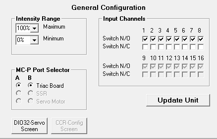
The configuration section of the LOR Control tab
Set the Minimum and Maximum Intensities
While active, the controller will not set its lights' intensities below the specified minimum. If, however, it loses communications with its director, it will turn them off (i.e. 0% intensity). The lights are not turned up to the minimum until the unit receives its first lighting command.
Setting a maximum intensity below 100% may be used to help prolong the life of bulbs, although there is an important exception: Retro LED C7 and C9 bulbs (also known as replacement LEDs) can be harmed by using them at any intensity other than 100% or 0%.
The initial values displayed in this section are read from the controller itself (although this is supported only for certain versions of firmware - your controller may need a firmware update in order to read the values from the controller).
These settings only take effect for ports that are configured as "Triac Board".

Setting the intensity range
The port type can be set to Triac Board, SSR, or Servo Motor. When set to Triac Board, dimming and fading are possible. When set to SSR, the unit will support SSRs with zero cross detectors. For the CTB08D controller, the two servo pins can be activated by setting Port B to Servo.

Setting the port type
Circuits that are used for interactive triggers can be either normally open ("N/O") or normally closed ("N/C"). The current value for each circuit is read from the controller itself, and the value can be updated in the "Input Channels" section.
Not all versions of firmware support this feature; if your controller has not yet been updated with firmware that supports it, the circuit will be treated as normally open (which is also the default for versions of firmware that can support both).

Setting the input channel types
DIO32 devices can be set up to control servos; the Hardware Utility can be used to configure them by clicking the "DIO32-Servo Screen" button in the Configuration section. Doing so brings up the following:

DIO32 servo configuration options
For each circuit, you can select the appropriate pulse width to be used for the servo attached to that circuit. There are at least two reasons why you might want to do this: First, some servos support different pulse widths than others; second, you might want to use this to limit the range of the servo.
The minimum value in the selected pulse width will be used whenever a 0% intensity is set on that circuit's channel; the maximum value will be used whenever a 100% intensity is set. Regardless of the pulse width, 50% intensity always corresponds to 1.5 milliseconds.
Note that only sixteen circuits are displayed, though the DIO32 has 32 circuits. This is because its 32 circuits are spread among two unit IDs. For example, the first sixteen circuits might be for unit ID 01, in which case the next sixteen would be for unit ID 02. Both sets of sixteen can be configured independently, by selecting the appropriate unit ID. However, if you want to configure both, make sure to update the controller with your changes for one before proceeding to the other.
Configuring Cosmic Color Ribbons
The Cosmic Color Ribbon has its own configuration options, unique to it. You can use the Hardware Utility to configure these options by clicking the "CCR-Config Screen" button in the Configuration section (note, though, that this button will be greyed out unless you have selected a Cosmic Color Ribbon unit; you may have to use the Refresh button in order to let the Hardware Utility know about your Cosmic Color Ribbon). Doing so will bring up the following screen:

Cosmic Color Ribbon configuration options
For details on these options, please refer to your Cosmic Color Ribbon manual (a PDF of the manual is available online at http://lightorama.com/Documents/CR150D_Man_Web.pdf). Here is a brief overview of each:
| • | Unit ID Mode: In "Normal" mode, the Cosmic Color Ribbon will be a single unit ID, with 157 circuit IDs. In "Legacy" mode, the Cosmic Color Ribbon will use up to ten sequential unit IDs (depending upon the configured resolution), with up to 16 circuit IDs for each unit ID. |
| • | Channel Mode: In "Triples" mode, channels will be arranged red, green, blue, red, green, blue, and so forth. For example, circuit 1 is red for the first pixel; circuit 2 green for the first pixel; circuit 3 blue for the first pixel; circuit 4 red for the second pixel; and so on. In "Sequential" mode, all red pixels will come first, then all green pixels, then all blue pixels. |
| • | Standalone Speed: The speed at which a standalone sequence will run. A value of 8 is normal speed; higher values are faster, and lower values are slower. |
| • | Resolution: The number of logical pixels that the Cosmic Color Ribbon will be. For example, setting it to 50 will give individual control over each of the 50 physical pixels, using 150 channels (one red, one green, and one blue for each pixel), while setting it to 1 will make all of the lights on the Cosmic Color Ribbon act as a single pixel, using three channels (red, green and blue). |
| • | Strips: The number of end-to-end connected ribbons. |
| • | DMX Mode: Selects how the Cosmic Color Ribbon will appear in a DMX universe: just the RGB channels, just the Macro channels, or both. |
After choosing the configuration options, make sure to update the unit with the new settings.
When you have set the configuration settings to the value you want, click the "Update Unit" button to send the new configuration information to the controller. Note: Doing so will update both the settings from the main screen and the settings from the DIO32 servo screen.
After updating, hit "Refresh" again to reload the new settings from the controller into the Hardware Utility.